4.1. Foreword
This document describes the FF-A implementation from [1] for the configuration where the SPMC resides at S-EL2 on platforms implementing the FEAT_SEL2 architecture extension.
It is not an architecture specification and it might provide assumptions on sections mandated as implementation-defined in the specification.
It covers the implications of TF-A used as a bootloader, and Hafnium used as a reference code base for an SPMC.
4.2. Terminology
The term Hypervisor refers to the NS-EL2 component managing Virtual Machines (or partitions) in the normal world.
The term SPMC refers to the S-EL2 component managing secure partitions in the secure world when the FEAT_SEL2 architecture extension is implemented.
Alternatively, SPMC can refer to an S-EL1 component, itself being a secure partition and implementing the FF-A ABI on platforms not implementing the FEAT_SEL2 architecture extension.
The term VM refers to a normal world Virtual Machine managed by an Hypervisor.
The term SP refers to a secure world “Virtual Machine” managed by an SPMC.
4.3. Sample reference stack
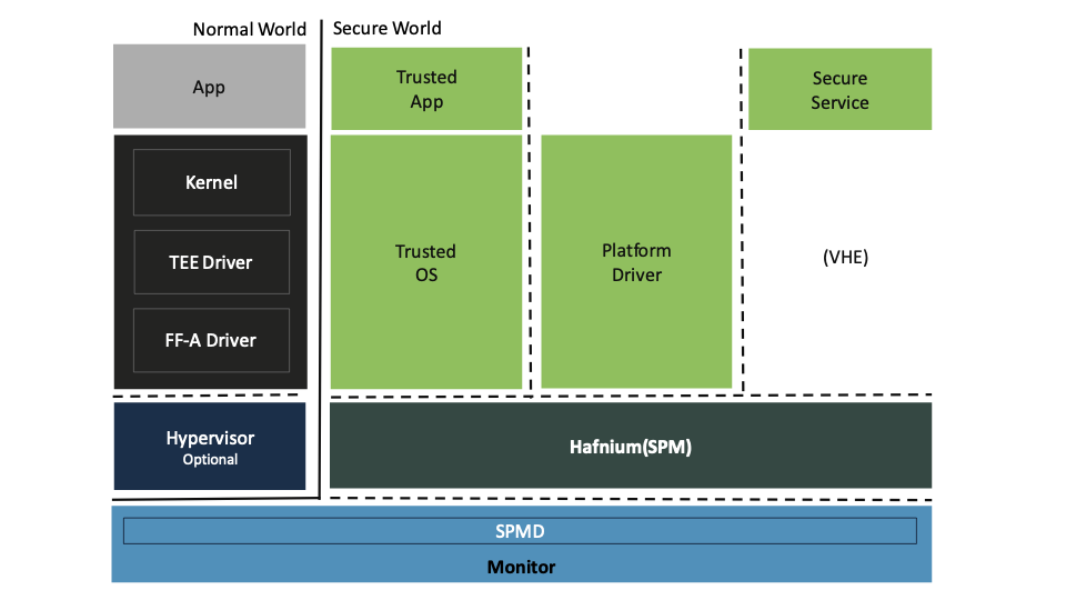
The following diagram illustrates a possible configuration when the FEAT_SEL2 architecture extension is implemented, showing the SPMD and SPMC, one or multiple secure partitions, with an optional Hypervisor:
4.4. Integration with TF-A (Bootloader and SPMD)
The TF-A project provides the reference implementation for the secure monitor for Arm A class devices, executing at EL3. It includes the implementation of the SPMD, which manages the world-switch, to relay the FF-A calls to the SPMC.
TF-A also serves as the system bootlader, and it was used in the reference implementation for the SPMC and SPs. SPs may be signed by different parties (SiP, OEM/ODM, TOS vendor, etc.). Thus they are supplied as distinct signed entities within the FIP flash image. The FIP image itself is not signed hence this provides the ability to upgrade SPs in the field.
4.4.1. TF-A build options
This section explains the TF-A build options for an FF-A based SPM, in which SPMD is located at EL3.
This is a step needed for integrating Hafnium as the S-EL2 SPMC and the TF-A as SPMD, together making the SPM component.
SPD=spmd: this option selects the SPMD component to relay the FF-A protocol from NWd to SWd back and forth. It is not possible to enable another Secure Payload Dispatcher when this option is chosen.
SPMD_SPM_AT_SEL2: this option adjusts the SPMC exception level to being at S-EL2. It defaults to enabled (value 1) when SPD=spmd is chosen.The context save/restore routine and exhaustive list of registers is visible at [4]. When set the reference software stack assumes enablement of FEAT_PAuth, FEAT_BTI and FEAT_MTE architecture extensions.
SP_LAYOUT_FILE: this option specifies a text description file providing paths to SP binary images and manifests in DTS format (see Secure Partitions Layout File). It is required when
SPMD_SPM_AT_SEL2is enabled, i.e. when multiple secure partitions are to be loaded by BL2 on behalf of the SPMC.BL32 option is re-purposed to specify the SPMC image. It can specify either the Hafnium binary path (built for the secure world) or the path to a TEE binary implementing FF-A interfaces.
BL33 option to specify normal world loader such as U-Boot or the UEFI framework payload, which would use FF-A calls during runtime to interact with Hafnium as the SPMC.
As a result of configuring SPD=spmd and SPMD_SPM_AT_SEL2 TF-A provides
context save/restore operations when entering/exiting an EL2 execution context.
There are other build options that relate support other valid FF-A system configurations where the SPMC is implemented at S-EL1 and EL3. Note that they conflict with those needed to integrate with Hafnium as the SPMC. For more details refer to TF-A build options [10].
Sample TF-A build command line when FEAT_SEL2 architecture extension is implemented and the SPMC is located at S-EL2, for Arm’s FVP platform:
make \
CROSS_COMPILE=aarch64-none-elf- \
PLAT=fvp \
SPD=spmd \
ARM_ARCH_MINOR=5 \
BRANCH_PROTECTION=1 \
ENABLE_FEAT_MTE2=1 \
BL32=<path-to-hafnium-binary> \
BL33=<path-to-bl33-binary> \
SP_LAYOUT_FILE=sp_layout.json \
all fip
Sample TF-A build command line when FEAT_SEL2 architecture extension is implemented, the SPMC is located at S-EL2, and enabling secure boot:
make \
CROSS_COMPILE=aarch64-none-elf- \
PLAT=fvp \
SPD=spmd \
ARM_ARCH_MINOR=5 \
BRANCH_PROTECTION=1 \
ENABLE_FEAT_MTE2=1 \
BL32=<path-to-hafnium-binary> \
BL33=<path-to-bl33-binary> \
SP_LAYOUT_FILE=sp_layout.json \
MBEDTLS_DIR=<path-to-mbedtls-lib> \
TRUSTED_BOARD_BOOT=1 \
COT=dualroot \
ARM_ROTPK_LOCATION=devel_rsa \
ROT_KEY=plat/arm/board/common/rotpk/arm_rotprivk_rsa.pem \
GENERATE_COT=1 \
all fip
4.4.2. FVP model invocation
Note
Hafnium testing (CI and local) is validated against Arm FVP release FM-11.31. Use the Base RevC AEMvA FVP model from this release (e.g. FVP_Base_RevC_AEMvA_11.31_28_Linux_x86), available from Arm’s website
The FVP command line needs the following options to exercise the S-EL2 SPMC:
|
Implements FEAT_SEL2, FEAT_PAuth, and FEAT_BTI. |
|
Parameters required for the SMMUv3.2 modeling. |
|
Implements FEAT_BTI. |
|
Implements FEAT_PAuth |
|
Implements FEAT_MTE2 |
Sample FVP command line invocation:
<path-to-fvp-model>/FVP_Base_RevC-2xAEMvA -C pctl.startup=0.0.0.0 \
-C cluster0.NUM_CORES=4 -C cluster1.NUM_CORES=4 -C bp.secure_memory=1 \
-C bp.secureflashloader.fname=trusted-firmware-a/build/fvp/debug/bl1.bin \
-C bp.flashloader0.fname=trusted-firmware-a/build/fvp/debug/fip.bin \
-C bp.pl011_uart0.out_file=fvp-uart0.log -C bp.pl011_uart1.out_file=fvp-uart1.log \
-C bp.pl011_uart2.out_file=fvp-uart2.log \
-C cluster0.has_arm_v8-5=1 -C cluster1.has_arm_v8-5=1 \
-C cluster0.has_pointer_authentication=2 -C cluster1.has_pointer_authentication=2 \
-C cluster0.bti_support_level=1 -C cluster1.bti_support_level=1 \
-C cluster0.memory_tagging_support_level=2 -C cluster1.memory_tagging_support_level=2 \
-C bp.dram_metadata.is_enabled=1 \
-C pci.pci_smmuv3.mmu.SMMU_AIDR=2 -C pci.pci_smmuv3.mmu.SMMU_IDR0=0x0046123B \
-C pci.pci_smmuv3.mmu.SMMU_IDR1=0x00600002 -C pci.pci_smmuv3.mmu.SMMU_IDR3=0x1714 \
-C pci.pci_smmuv3.mmu.SMMU_IDR5=0xFFFF0472 -C pci.pci_smmuv3.mmu.SMMU_S_IDR1=0xA0000002 \
-C pci.pci_smmuv3.mmu.SMMU_S_IDR2=0 -C pci.pci_smmuv3.mmu.SMMU_S_IDR3=0
4.5. SPMC Configuration
This section details the configuration files required to deploy Hafnium as the SPMC, along with those required to configure each secure partion.
4.5.1. SPMC Manifest
This manifest contains the SPMC attribute node consumed by the SPMD at boot time. It implements [1] (SP manifest at physical FF-A instance) and serves two different cases:
The SPMC manifest is used by the SPMD to setup the environment required by the SPMC to run at S-EL2. SPs run at S-EL1 or S-EL0.
attribute {
    spmc_id = <0x8000>;
    maj_ver = <0x1>;
    min_ver = <0x1>;
    exec_state = <0x0>;
    load_address = <0x0 0x6000000>;
    entrypoint = <0x0 0x6000000>;
    binary_size = <0x60000>;
};
spmc_id defines the endpoint ID value that SPMC can query through
FFA_ID_GET.maj_ver/min_ver. SPMD checks provided FF-A version versus its internal version and aborts if not matching.
exec_state defines the SPMC execution state (AArch64 or AArch32). Notice Hafnium used as a SPMC only supports AArch64.
load_address and binary_size are mostly used to verify secondary entry points fit into the loaded binary image.
entrypoint defines the cold boot primary core entry point used by SPMD (currently matches
BL32_BASE) to enter the SPMC.
Other nodes in the manifest are consumed by Hafnium in the secure world. A sample can be found at [7]:
The hypervisor node describes SPs. is_ffa_partition boolean attribute indicates a FF-A compliant SP. The load_address field specifies the load address at which BL2 loaded the partition package.
The cpus node provides the platform topology and allows MPIDR to VMPIDR mapping. Note the primary core is declared first, then secondary cores are declared in reverse order.
The memory nodes provide platform information on the ranges of memory available for use by SPs at runtime. These ranges relate to either normal or device and secure or non-secure memory, depending on the device_type field. The system integrator must exclude the memory used by other components that are not SPs, such as the monitor, or the SPMC itself, the OS Kernel/Hypervisor, NWd VMs, or peripherals that shall not be used by any of the SPs. The following are the supported device_type fields:
“memory”: normal secure memory.
“ns-memory”: normal non-secure memory.
“device-memory”: device secure memory.
“ns-device-memory”: device non-secure memory.
The SPMC limits the SP’s address space such that they can only refer to memory inside of those ranges, either by defining memory region or device region nodes in their manifest as well as memory starting at the load address until the limit defined by the memory size. The SPMC also checks for overlaps between the regions. Thus, the SPMC prevents rogue SPs from tampering with memory from other components.
memory@0 {
        device_type = "memory";
        reg = <0x0 0x6000000 0x2000000 0x0 0xff000000 0x1000000>;
};

memory@1 {
        device_type = "ns-memory";
        reg = <0x0 0x90010000 0x70000000>;
};

memory@2 {
        device_type = "device-memory";
        reg = <0x0 0x1c090000 0x0 0x40000>, /* UART */
              <0x0 0x2bfe0000 0x0 0x20000>, /* SMMUv3TestEngine */
              <0x0 0x2a490000 0x0 0x10000>, /* SP805 Trusted Watchdog */
              <0x0 0x1c130000 0x0 0x10000>; /* Virtio block device */
};

memory@3 {
        device_type = "ns-device-memory";
        reg = <0x0 0x1C1F0000 0x0 0x10000>; /* LCD */
};
Above find an example representation of the referred memory description. The ranges are described in a list of unsigned 32-bit values, in which the first two addresses relate to the based physical address, followed by the respective page size. The first secure range defined in the node below has base address 0x0 0x6000000 and size 0x2000000; following there is another range with base address 0x0 0xff000000 and size 0x1000000.
The interrupt-controller node contains the address ranges of GICD and GICR so that non-contiguous GICR frames can be probed during boot flow. The GICD addresses are defined first in the cells, followed by the GICR addresses, then SPI ID ranges for all chips. “distributor-regions” is used to define the number of GICD addresses. “redistributor-regions” is used to define the number of GICR addresses. “spi_regions” is used to define the number of SPI ID ranges.
This node is optional. When absent, the default configuration assumes there is
one distributor, redistributor and SPI region.
The default GICD memory range is from GICD_BASE to GICD_BASE + GICD_SIZE.
The default GICR memory range is from GICR_BASE to GICR_BASE + GICR_FRAMES * GIC_REDIST_SIZE_PER_PE.
All SPIs are directed to chip 0.
To enable support on multi chip platforms, this node is mandatory. Each chip need to have one GICD memory range, one or more GICR memory ranges and one SPI ID range.
The sum of distributor-regions, redistributor-regions and spi-regions must equal the number of entries in field reg.
gic: interrupt-controller@0x30000000 {
        compatible = "arm,gic-v3";
        #address-cells = <2>;
        #size-cells = <1>;
        #distributor-regions = <2>;
        #redistributor-regions = <2>;
        #spi-regions = <2>;
        reg = <0x00 0x30000000 0x10000>,        // GICD 0: Chip 0
              <0x10 0x30000000 0x10000>,        // GICD 1: Chip 1
              <0x00 0x301C0000 0x400000>,       // GICR 0: Chip 0
              <0x10 0x301C0000 0x400000>,       // GICR 1: Chip 1
              <0x00 0x00000020 0x0001DF>,       // SPI: Chip 0
              <0x00 0x00000200 0x0001DF>;       // SPI: Chip 1
};
The above is an example representation of the referred interrupt controller description. The cells are made up of three values. The first two 32-bit values make up a 64-bit value representing the address of the GIC redistributor. The third value represents the size of this region. In this example, redistributor-regions states there are 2 GICD cell, GICR cells and SPI cells. The address of GICD 0 is 0x0030000000 and the size of that region is 0x10000. The address of GICR 0 is 0x00301C0000 and the size of that region is 0x400000. The SPI block of Chip 0 starts from 0x20 and contains 0x1DF SPIs.
4.5.2. Secure Partitions Configuration
4.5.2.1. SP Manifests
An SP manifest describes SP attributes as defined in [1] (partition manifest at virtual FF-A instance) in DTS format. It is represented as a single file associated with the SP. A sample is provided by [5]. A binding document is provided by [6].
4.5.2.2. Platform topology
The execution-ctx-count SP manifest field can take the value of one or the total number of PEs. The FF-A specification [1] recommends the following SP types:
Pinned MP SPs: an execution context matches a physical PE. MP SPs must implement the same number of ECs as the number of PEs in the platform.
Migratable UP SPs: a single execution context can run and be migrated on any physical PE. Such SP declares a single EC in its SP manifest. An UP SP can receive a direct message request originating from any physical core targeting the single execution context.
4.5.2.3. Secure Partition packages
Secure partitions are bundled as independent package files. Current supported partition package types are a Secure Partition Package or a Transfer List Package.
The partition package type can be specified in the SP Layout of the SP (see section Secure Partitions Layout File).
A Secure Partition package is an implementation defined format that includes:
a header
a DTB
an image payload
A Transfer List (TL) package type should include an entry for the image and an entry for the DTB using the Transfer Entry format. The TL package can also use other Transfer Entry types to include optional platform-specific boot information to be passed to the SP, such as a HOB list. More information on Transfer Lists can be found in the Firmware Handoff specification.
The header starts with a magic value and offset values to SP DTB and image payload. Each partition package is loaded independently by BL2 loader and verified for authenticity and integrity.
The partition package identified by its UUID (matching FF-A uuid property) is inserted as a single entry into the FIP at end of the TF-A build flow as shown:
Trusted Boot Firmware BL2: offset=0x1F0, size=0x8AE1, cmdline="--tb-fw"
EL3 Runtime Firmware BL31: offset=0x8CD1, size=0x13000, cmdline="--soc-fw"
Secure Payload BL32 (Trusted OS): offset=0x1BCD1, size=0x15270, cmdline="--tos-fw"
Non-Trusted Firmware BL33: offset=0x30F41, size=0x92E0, cmdline="--nt-fw"
HW_CONFIG: offset=0x3A221, size=0x2348, cmdline="--hw-config"
TB_FW_CONFIG: offset=0x3C569, size=0x37A, cmdline="--tb-fw-config"
SOC_FW_CONFIG: offset=0x3C8E3, size=0x48, cmdline="--soc-fw-config"
TOS_FW_CONFIG: offset=0x3C92B, size=0x427, cmdline="--tos-fw-config"
NT_FW_CONFIG: offset=0x3CD52, size=0x48, cmdline="--nt-fw-config"
B4B5671E-4A90-4FE1-B81F-FB13DAE1DACB: offset=0x3CD9A, size=0xC168, cmdline="--blob"
D1582309-F023-47B9-827C-4464F5578FC8: offset=0x48F02, size=0xC168, cmdline="--blob"
![/'
' Copyright (c) 2020-2023, ARM Limited and Contributors. All rights reserved.
'
' SPDX-License-Identifier: BSD-3-Clause
'/
@startuml
folder SP_vendor_1 {
artifact sp_binary_1
artifact sp_manifest_1 [
sp_manifest_1
===
UUID = xxx
load_address = 0xaaa
owner = "Sip"
...
]
}
folder SP_vendor_2 {
artifact sp_binary_2
artifact sp_manifest_2 [
sp_manifest_2
===
UUID = yyy
load_address = 0xbbb
owner = "Plat"
]
}
artifact tb_fw_config.dts [
tb_fw_config.dts
----
secure-partitions
===
spkg_1 UUID
spkg_1 load_address
---
spkg_2 UUID
spkg_2 load_address
---
...
===
...<rest of the nodes>
]
artifact config.json [
SP_LAYOUT.json
===
path to sp_binary_1
path to sp_manifest_1
---
path to sp_binary_2
path to sp_manifest_2
---
...
]
control sp_mk_generator
artifact sp_gen [
sp_gen.mk
===
FDT_SOURCE = ...
SPTOOL_ARGS = ...
FIP_ARGS = ...
CRT_ARGS = ...
]
control dtc
control sptool
artifact tb_fw_config.dtb
artifact spkg_1 [
sp1.pkg
===
<i>header</i>
---
manifest
---
binary
]
artifact spkg_2 [
sp2.pkg
===
<i>header</i>
---
manifest
---
binary
]
artifact signed_tb_fw_config.dtb [
tb_fw_config.dtb (signed)
]
artifact signed_spkg_1 [
sp1.pkg (signed)
===
<i>header</i>
---
manifest
---
binary
---
<i>signature</I>
]
artifact signed_spkg_2 [
sp2.pkg (signed)
===
<i>header</i>
---
manifest
---
binary
---
<i>signature</I>
]
control crttool
control fiptool
artifact fip [
fip.bin
===
tb_fw_config.dtb (signed)
---
...
---
sp1.pkg (signed & SiP owned)
---
sp2.pkg (signed & Platform owned)
---
...
]
config.json .up.> SP_vendor_1
config.json .up.> SP_vendor_2
config.json --> sp_mk_generator
sp_mk_generator --> sp_gen
sp_gen --> fiptool
sp_gen --> cert_create
sp_gen --> sptool
sptool --> spkg_1
sptool --> spkg_2
spkg_1 --> cert_create
spkg_2 --> cert_create
cert_create --> signed_spkg_1
cert_create --> signed_spkg_2
tb_fw_config.dts --> dtc
dtc --> tb_fw_config.dtb
tb_fw_config.dtb --> cert_create
cert_create --> signed_tb_fw_config.dtb
signed_tb_fw_config.dtb --> fiptool
signed_spkg_1 -down-> fiptool
signed_spkg_2 -down-> fiptool
fiptool -down-> fip
@enduml](../_images/plantuml-2c741ff3c05a93b342fa09fedb0e72a2a84c23fc.svg)
4.5.2.4. Secure Partitions Layout File
A json-formatted description file is passed to the build flow specifying paths to the SP binary image and associated DTS partition manifest file. The latter is processed by the dtc compiler to generate a DTB fed into the partition package. Each partition can be configured with the following fields:
imageSpecifies the filename and offset of the image within the partition package.
Can be written as
"image": { "file": "path", "offset": 0x1234 }to give bothimage.fileandimage.offsetvalues explicitly, or can be written as"image": "path"to giveimage.fileand value and leaveimage.offsetabsent.
image.fileSpecifies the filename of the image.
image.offsetSpecifies the offset of the image within the partiton package.
Must be 4KB aligned, because that is the translation granule supported by Hafnium SPMC.
Optional. Defaults to
0x4000.
pmSpecifies the filename and offset of the partition manifest within the partition package.
Can be written as
"pm": { "file": "path", "offset": 0x1234 }to give bothpm.fileandpm.offsetvalues explicitly, or can be written as"pm": "path"to givepm.fileand value and leavepm.offsetabsent.
pm.fileSpecifies the filename of the partition manifest.
pm.offsetSpecifies the offset of the partition manifest within the partition package.
Must be 4KB aligned, because that is the translation granule supported by Hafnium SPMC.
Optional. Defaults to
0x1000.
image.offset and pm.offset can be leveraged to support SPs with
S1 translation granules that differ from 4KB, and to configure the regions
allocated within the partition package, as well as to comply with the requirements for
the implementation of the boot information protocol (see Passing boot data to
the SP for more details).
ownerSpecifies the SP owner, identifying the signing domain in case of dual root CoT.
Possible values are
SiP(silicon owner) orPlat(platform owner).Optional. Defaults to
SiP.
uuidSpecifies the UUID of the partition.
Optional. Defaults to the value of the
uuidfield from the DTS partition manifest.
physical-load-addressSpecifies the
load_addressfield of the generated DTS fragment.Optional. Defaults to the value of the
load-addressfrom the DTS partition manifest.
packageSpecifies the package type of the partition package.
Optional. Defaults to the value of
sp_pkg.
sizeSpecifies the size in bytes of the partition package.
Optional. Defaults to
0x100000.
{
    "tee1" : {
        "image": "tee1.bin",
         "pm": "tee1.dts",
         "owner": "SiP",
         "uuid": "1b1820fe-48f7-4175-8999-d51da00b7c9f"
    },

    "tee2" : {
        "image": "tee2.bin",
        "pm": "tee2.dts",
        "owner": "Plat"
    },

    "tee3" : {
        "image": {
            "file": "tee3.bin",
            "offset":"0x2000"
         },
        "pm": {
            "file": "tee3.dts",
            "offset":"0x6000"
         },
        "owner": "Plat",
        "package": "tl_pkg",
        "size": "0x100000"
    },
}
4.6. SPMC boot
The SPMC is loaded by BL2 as the BL32 image.
The SPMC manifest is loaded by BL2 as the TOS_FW_CONFIG image [9].
BL2 passes the SPMC manifest address to BL31 through a register.
At boot time, the SPMD in BL31 runs from the primary core, initializes the core contexts and launches the SPMC (BL32) passing the following information through registers:
X0 holds the
TOS_FW_CONFIGphysical address (or SPMC manifest blob).X1 holds the
HW_CONFIGphysical address.X4 holds the currently running core linear id.
4.6.1. Secure boot
The SP content certificate is inserted as a separate FIP item so that BL2 loads SPMC, SPMC manifest, secure partitions and verifies them for authenticity and integrity. Refer to TBBR specification [3].
The multiple-signing domain feature (in current state dual signing domain [8]) allows the use of two root keys namely S-ROTPK and NS-ROTPK:
SPMC (BL32) and SPMC manifest are signed by the SiP using the S-ROTPK.
BL33 may be signed by the OEM using NS-ROTPK.
An SP may be signed either by SiP (using S-ROTPK) or by OEM (using NS-ROTPK).
A maximum of 4 partitions can be signed with the S-ROTPK key and 4 partitions signed with the NS-ROTPK key.
Also refer to Secure Partitions Configuration and TF-A build options sections.
4.6.2. Boot phases
4.6.2.1. Primary core boot-up
Upon boot-up, BL31 hands over to the SPMC (BL32) on the primary boot physical core. The SPMC performs its platform initializations and registers the SPMC secondary physical core entry point physical address by the use of the FFA_SECONDARY_EP_REGISTER interface (SMC invocation from the SPMC to the SPMD at secure physical FF-A instance).
The SPMC then creates secure partitions based on partition packages and manifests. Each secure partition is launched in sequence (SP Boot order) on their “primary” execution context. If the primary boot physical core linear id is N, an MP SP is started using EC[N] on PE[N] (see Platform topology). If the partition is a UP SP, it is started using its unique EC0 on PE[N].
The SP primary EC (or the EC used when the partition is booted as described above):
Performs the overall SP boot time initialization, and in case of a MP SP, prepares the SP environment for other execution contexts.
In the case of a MP SP, it invokes the FFA_SECONDARY_EP_REGISTER at secure virtual FF-A instance (SMC invocation from SP to SPMC) to provide the IPA entry point for other execution contexts.
Exits through
FFA_MSG_WAITto indicate successful initialization orFFA_ERRORin case of failure.
4.6.2.2. Secondary cores boot-up
Once the system is started and NWd brought up, a secondary physical core is
woken up by the PSCI_CPU_ON service invocation. The TF-A SPD hook mechanism
calls into the SPMD on the newly woken up physical core. Then the SPMC is
entered at the secondary physical core entry point.
As per secondary boot protocol described in section 18.2.2 of the FF-A v1.3ALP1 specification, each pinned execution context of every MP SP is woken up by SPMC, thereby giving an opportunity to the MP SP’s EC on secondary core to initialize itself. Upon successful initialization, the EC relinquishes CPU cycles through FFA_MSG_WAIT ABI and moves to WAITING state.
Note that an UP SP does not have a pinned execution context. Hence, if a system only has UP SPs, then there are no pinned execution contexts to be resumed on secondary cores.
In a linux based system, once secure and normal worlds are booted but prior to a NWd FF-A driver has been loaded:
Every MP SP has initialized its primary EC in response to primary core boot up (at system initialization) and secondary ECs in response to secondary cores boot up (as a result of linux invoking PSCI_CPU_ON for all secondary cores). If there are multiple MP SPs deployed, the order in which their respective ECs are woken up is determined by the boot-order field in the partition manifests.
Every UP SP has its only EC initialized as a result of secure world initialization on the primary boot core.
Refer to Power management for further details.
4.6.3. Loading of SPs
At boot time, BL2 loads SPs sequentially in addition to the SPMC as depicted below:

Note this boot flow is an implementation sample on Arm’s FVP platform. Platforms not using TF-A’s Firmware CONFiguration framework would adjust to a different boot flow. The flow restricts to a maximum of 8 secure partitions.
4.6.3.1. SP Boot order
SP manifests provide an optional boot order attribute meant to resolve dependencies such as an SP providing a service required to properly boot another SP. SPMC boots the SPs in accordance to the boot order attribute, lowest to the highest value. If the boot order attribute is absent from the FF-A manifest, the SP is treated as if it had the highest boot order value (i.e. lowest booting priority). The FF-A specification mandates this field is unique to each SP.
It is possible for an SP to call into another SP through a direct request provided the latter SP has already been booted.
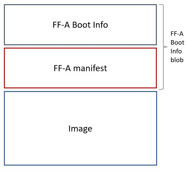
4.6.3.2. Passing boot data to the SP
In [1] , the section “Boot information protocol” defines a method for passing data to the SPs at boot time. It specifies the format for the boot information descriptor and boot information header structures, which describe the data to be exchanged between SPMC and SP. The specification also defines the types of data that can be passed. The aggregate of both the boot info structures and the data itself is designated the boot information blob, and is passed to a Partition as a contiguous memory region.
Currently, the SPM implementation supports the FDT type, which is used to pass the partition’s DTB manifest, and the Hand-off Block (HOB) list type.
The region for the boot information blob is allocated through the partition package.
To adjust the space allocated for the boot information blob, the json description of the SP (see section Secure Partitions Layout File) shall be updated to contain the manifest offset. If no offset is provided the manifest offset defaults to 0x1000, which is the page size in the Hafnium SPMC.
Currently, the SPM implementation does not yet support specifying the offset for the HOB list in the json description of the SP. A default value of 0x2000 is used.
The configuration of the boot protocol is done in the SPs manifest. As defined by the specification, the manifest field ‘gp-register-num’ configures the GP register which shall be used to pass the address to the partitions boot information blob when booting the partition. In addition, the Hafnium SPMC implementation requires the boot information arguments to be listed in a designated DT node:
boot-info {
    compatible = "arm,ffa-manifest-boot-info";
    ffa_manifest;
};
boot-info {
    compatible = "arm,ffa-manifest-boot-info";
    hob_list;
};
The whole secure partition package image (see Secure Partition packages) is mapped to the SP secure EL1&0 Stage-2 translation regime. As such, the SP can retrieve the address for the boot information blob in the designated GP register, process the boot information header and descriptors, access its own manifest DTB blob or HOB list and extract its properties.
4.7. SPMC Runtime
4.7.1. Parsing SP partition manifests
Hafnium consumes SP manifests as defined in [1] and SP manifests. Note the current implementation may not implement all optional fields.
The SP manifest may contain memory and device regions nodes:
Memory regions are mapped in the SP EL1&0 Stage-2 translation regime at load time (or EL1&0 Stage-1 for an S-EL1 SPMC). A memory region node can specify RX/TX buffer regions in which case it is not necessary for an SP to explicitly invoke the
FFA_RXTX_MAPinterface. The memory referred shall be contained within the memory ranges defined in SPMC manifest. The NS bit in the attributes field should be consistent with the security state of the range that it relates to. I.e. non-secure memory shall be part of a non-secure memory range, and secure memory shall be contained in a secure memory range of a given platform.Device regions are mapped in the SP EL1&0 Stage-2 translation regime (or EL1&0 Stage-1 for an S-EL1 SPMC) as peripherals and possibly allocate additional resources (e.g. interrupts).
For the SPMC, base addresses for memory and device region nodes are IPAs provided the SPMC identity maps IPAs to PAs within SP EL1&0 Stage-2 translation regime.
ote: in the current implementation both VTTBR_EL2 and VSTTBR_EL2 point to the same set of page tables. It is still open whether two sets of page tables shall be provided per SP. The memory region node as defined in the specification provides a memory security attribute hinting to map either to the secure or non-secure EL1&0 Stage-2 table if it exists.
4.7.2. Secure partitions scheduling
The FF-A specification [1] provides two ways to allocate CPU cycles to secure partitions. For this a VM (Hypervisor or OS kernel), or SP invokes one of:
the FFA_MSG_SEND_DIRECT_REQ (or FFA_MSG_SEND_DIRECT_REQ2) interface.
the FFA_RUN interface.
Additionally a secure interrupt can pre-empt the normal world execution and give CPU cycles by transitioning to EL3 and S-EL2.
4.7.3. Mandatory interfaces
The following interfaces are exposed to SPs:
FFA_VERSIONFFA_FEATURESFFA_RX_RELEASEFFA_RXTX_MAPFFA_RXTX_UNMAPFFA_PARTITION_INFO_GETFFA_ID_GETFFA_MSG_WAITFFA_MSG_SEND_DIRECT_REQFFA_MSG_SEND_DIRECT_RESPFFA_MEM_DONATEFFA_MEM_LENDFFA_MEM_SHAREFFA_MEM_RETRIEVE_REQFFA_MEM_RETRIEVE_RESPFFA_MEM_RELINQUISHFFA_MEM_FRAG_RXFFA_MEM_FRAG_TXFFA_MEM_RECLAIMFFA_RUN
As part of the FF-A v1.1 support, the following interfaces were added:
FFA_NOTIFICATION_BITMAP_CREATE
FFA_NOTIFICATION_BITMAP_DESTROY
FFA_NOTIFICATION_BIND
FFA_NOTIFICATION_UNBIND
FFA_NOTIFICATION_SET
FFA_NOTIFICATION_GET
FFA_NOTIFICATION_INFO_GET
FFA_SPM_ID_GET
FFA_SECONDARY_EP_REGISTER
FFA_MEM_PERM_GET
FFA_MEM_PERM_SET
FFA_MSG_SEND2
FFA_RX_ACQUIRE
As part of the FF-A v1.2 support, the following interfaces were added:
FFA_PARTITION_INFO_GET_REGSFFA_MSG_SEND_DIRECT_REQ2FFA_MSG_SEND_DIRECT_RESP2FFA_CONSOLE_LOG
4.7.3.1. FFA_VERSION
FFA_VERSION requires a requested_version parameter from the caller.
The returned value depends on the caller:
Hypervisor or OS kernel in NS-EL1/EL2: the SPMD returns the SPMC version specified in the SPMC manifest.
SP: the SPMC returns its own implemented version.
SPMC at S-EL1/S-EL2: the SPMD returns its own implemented version.
The FF-A version can only be changed by calls to FFA_VERSION before other
calls to other FF-A ABIs have been made. Calls to FFA_VERSION after
subsequent ABI calls will fail.
4.7.3.2. FFA_FEATURES
FF-A features supported by the SPMC may be discovered by secure partitions at boot (that is prior to NWd is booted) or run-time.
The SPMC calling FFA_FEATURES at secure physical FF-A instance always get FFA_SUCCESS from the SPMD.
S-EL1 partitions calling FFA_FEATURES at virtual FF-A instance with NPI and MEI interrupt feature IDs get FFA_SUCCESS.
S-EL0 partitions are not supported for NPI: FFA_NOT_SUPPORTED will be
returned.
Physical FF-A instances are not supported for NPI and MEI: FFA_NOT_SUPPORTED
will be returned.
The request made by an Hypervisor or OS kernel is forwarded to the SPMC and the response relayed back to the NWd.
4.7.3.3. FFA_RXTX_MAP/FFA_RXTX_UNMAP
When invoked from a secure partition FFA_RXTX_MAP maps the provided send and receive buffers described by their IPAs to the SP EL1&0 Stage-2 translation regime as secure buffers in the MMU descriptors.
When invoked from the Hypervisor or OS kernel, the buffers are mapped into the SPMC EL2 Stage-1 translation regime and marked as NS buffers in the MMU descriptors. The provided addresses may be owned by a VM in the normal world, which is expected to receive messages from the secure world. The SPMC will in this case allocate internal state structures to facilitate RX buffer access synchronization (through FFA_RX_ACQUIRE interface), and to permit SPs to send messages. The addresses used must be contained in the SPMC manifest NS memory node (see SPMC manifest).
The FFA_RXTX_UNMAP unmaps the RX/TX pair from the translation regime of the caller, either it being the Hypervisor or OS kernel, as well as a secure partition, and restores them in the VM’s translation regime so that they can be used for memory sharing operations from the normal world again.
The minimum and maximum buffer sizes supported by the FF-A instance can be
queried by calling FFA_FEATURES with the FFA_RXTX_MAP function ID.
4.7.3.4. FFA_PARTITION_INFO_GET/FFA_PARTITION_INFO_GET_REGS
Partition info get call can originate:
from SP to SPMC
from Hypervisor or OS kernel to SPMC. The request is relayed by the SPMD.
from SPMC to SPMD (FFA_PARTITION_INFO_GET_REGS only)
The primary use of the FFA_PARTITION_INFO_GET_REGS is to return partition information via registers as opposed to via RX/TX buffers and is useful in cases where sharing memory is difficult.
The SPMC reports the features supported by an SP in accordance to the caller. E.g. SPs can’t issue direct message requests to the Normal World. As such, even though SP may have enabled sending direct message requests in the manifest, the respective SP’s properties information will hint that the SP doesn’t support sending direct message requests.
The information is also filtered by FF-A version. E.g. indirect message support in Hafnium was added in FF-A v1.1. An FF-A v1.0 caller will not get indirect message support for an SP, even if the SP is v1.1 or higher, and has enabled indirect messaging in its manifest.
4.7.3.5. FFA_ID_GET
The FF-A id space is split into a non-secure space and secure space:
FF-A ID with bit 15 clear relates to VMs.
FF-A ID with bit 15 set related to SPs.
FF-A IDs 0, 0xffff, 0x8000 are assigned respectively to the Hypervisor, SPMD and SPMC.
The SPMD returns:
The default zero value on invocation from the Hypervisor.
The
spmc_idvalue specified in the SPMC manifest on invocation from the SPMC (see SPMC manifest)
This convention helps the SPMC to determine the origin and destination worlds in an FF-A ABI invocation. In particular the SPMC shall filter unauthorized transactions in its world switch routine. It must not be permitted for a VM to use a secure FF-A ID as origin world by spoofing:
A VM-to-SP direct request/response shall set the origin world to be non-secure (FF-A ID bit 15 clear) and destination world to be secure (FF-A ID bit 15 set).
Similarly, an SP-to-SP direct request/response shall set the FF-A ID bit 15 for both origin and destination IDs.
An incoming direct message request arriving at SPMD from NWd is forwarded to SPMC without a specific check. The SPMC is resumed through eret and “knows” the message is coming from normal world in this specific code path. Thus the origin endpoint ID must be checked by SPMC for being a normal world ID.
An SP sending a direct message request must have bit 15 set in its origin endpoint ID and this can be checked by the SPMC when the SP invokes the ABI.
The SPMC shall reject the direct message if the claimed world in origin endpoint ID is not consistent:
It is either forwarded by SPMD and thus origin endpoint ID must be a “normal world ID”,
or initiated by an SP and thus origin endpoint ID must be a “secure world ID”.
4.7.3.6. FFA_MSG_WAIT
FFA_MSG_WAIT is used to transition the calling execution context from the RUNNING state to the WAITING state, subject to the restrictions of the partition’s current runtime model (see Partition runtime models).
Secondarily, an invocation of FFA_MSG_WAIT will relinquish ownership of the caller’s RX buffer to the buffer’s producer. FF-A v1.2 introduces the ability to optionally retain the buffer on an invocation of FFA_MSG_WAIT through use of a flag.
4.7.3.7. FFA_MSG_SEND_DIRECT_REQ/FFA_MSG_SEND_DIRECT_RESP
This is a mandatory interface for secure partitions consisting in direct request and responses with the following rules:
An SP can send a direct request to another SP.
An SP can receive a direct request from another SP.
An SP can send a direct response to another SP.
An SP cannot send a direct request to an Hypervisor or OS kernel.
An Hypervisor or OS kernel can send a direct request to an SP.
An SP can send a direct response to an Hypervisor or OS kernel.
An SP cannot reply to a framework direct request with a non-framework direct response.
The hypervisor can inform SPs when a VM is created or destroyed by sending VM
availability messages via the FFA_MSG_SEND_DIRECT_REQ ABI.
A SP subscribes to receiving VM created and/or VM destroyed messages by
specifying the vm-availability-messages field in its manifest (see
partition properties). The SPM will only forward messages to the SP if the SP
is subscribed to the message kind. The SP must reply with the corresponding
direct message response (via the FFA_MSG_SEND_DIRECT_RESP ABI) after it has
handled the message.
4.7.3.8. FFA_MSG_SEND_DIRECT_REQ2/FFA_MSG_SEND_DIRECT_RESP2
The primary usage of these ABIs is to send a direct request to a specified UUID within an SP that has multiple UUIDs declared in its manifest.
Secondarily, it can be used to send a direct request with an extended set of message payload arguments.
4.7.3.9. FFA_NOTIFICATION_BITMAP_CREATE/FFA_NOTIFICATION_BITMAP_DESTROY
The secure partitions notifications bitmap are statically allocated by the SPMC. Hence, this interface is not to be issued by secure partitions.
At initialization, the SPMC is not aware of VMs/partitions deployed in the normal world. Hence, the Hypervisor or OS kernel must use both ABIs for SPMC to be prepared to handle notifications for the provided VM ID.
4.7.3.10. FFA_NOTIFICATION_BIND/FFA_NOTIFICATION_UNBIND
Pair of interfaces to manage permissions to signal notifications. Prior to handling notifications, an FF-A endpoint must allow a given sender to signal a bitmap of notifications.
If the receiver doesn’t have notification support enabled in its FF-A manifest, it won’t be able to bind notifications, hence forbidding it to receive any notifications.
4.7.3.11. FFA_NOTIFICATION_SET/FFA_NOTIFICATION_GET
FFA_NOTIFICATION_GET retrieves all pending global notifications and per-vCPU notifications targeted to the current vCPU.
Hafnium maintains a global count of pending notifications which gets incremented and decremented when handling FFA_NOTIFICATION_SET and FFA_NOTIFICATION_GET respectively. A delayed SRI is triggered if the counter is non-zero when the SPMC returns to normal world.
4.7.3.12. FFA_NOTIFICATION_INFO_GET
Hafnium maintains a global count of pending notifications whose information has been retrieved by this interface. The count is incremented and decremented when handling FFA_NOTIFICATION_INFO_GET and FFA_NOTIFICATION_GET respectively. It also tracks notifications whose information has been retrieved individually, such that it avoids duplicating returned information for subsequent calls to FFA_NOTIFICATION_INFO_GET. For each notification, this state information is reset when receiver called FFA_NOTIFICATION_GET to retrieve them.
4.7.3.13. FFA_SPM_ID_GET
Returns the FF-A ID allocated to an SPM component which can be one of SPMD or SPMC.
At initialization, the SPMC queries the SPMD for the SPMC ID, using the FFA_ID_GET interface, and records it. The SPMC can also query the SPMD ID using the FFA_SPM_ID_GET interface at the secure physical FF-A instance.
Secure partitions call this interface at the virtual FF-A instance, to which the SPMC returns the priorly retrieved SPMC ID.
The Hypervisor or OS kernel can issue the FFA_SPM_ID_GET call handled by the SPMD, which returns the SPMC ID.
4.7.3.14. FFA_SECONDARY_EP_REGISTER
When the SPMC boots, all secure partitions are initialized on their primary Execution Context.
The FFA_SECONDARY_EP_REGISTER interface is to be used by a secure partition from its first execution context, to provide the entry point address for secondary execution contexts.
A secondary EC is first resumed either upon invocation of PSCI_CPU_ON from the NWd or by invocation of FFA_RUN.
4.7.3.15. FFA_RX_ACQUIRE/FFA_RX_RELEASE
The RX buffers can be used to pass information to an FF-A endpoint in the following scenarios:
When it was targetted by a FFA_MSG_SEND2 invokation from another endpoint.
Return the result of calling
FFA_PARTITION_INFO_GET.In a memory share operation, as part of the
FFA_MEM_RETRIEVE_RESP, with the memory descriptor of the shared memory.
If a normal world VM is expected to exchange messages with secure world, its RX/TX buffer addresses are forwarded to the SPMC via FFA_RXTX_MAP ABI, and are from this moment owned by the SPMC. The hypervisor must call the FFA_RX_ACQUIRE interface before attempting to use the RX buffer, in any of the aforementioned scenarios. A successful call to FFA_RX_ACQUIRE transfers ownership of RX buffer to hypervisor, such that it can be safely used.
The FFA_RX_RELEASE interface is used after the FF-A endpoint is done with processing the data received in its RX buffer. If the RX buffer has been acquired by the hypervisor, the FFA_RX_RELEASE call must be forwarded to the SPMC to reestablish SPMC’s RX ownership.
An attempt from an SP to send a message to a normal world VM whose RX buffer was acquired by the hypervisor fails with error code FFA_BUSY, to preserve the RX buffer integrity. The operation could then be conducted after FFA_RX_RELEASE.
4.7.3.16. FFA_MSG_SEND2
Hafnium copies a message from the sender TX buffer into receiver’s RX buffer. For messages from SPs to VMs, operation is only possible if the SPMC owns the receiver’s RX buffer.
Both receiver and sender need to enable support for indirect messaging, in their respective partition manifest. The discovery of support of such feature can be done via FFA_PARTITION_INFO_GET.
On a successful message send, Hafnium pends an RX buffer full framework notification for the receiver, to inform it about a message in the RX buffer.
The handling of framework notifications is similar to that of global notifications. Binding of these is not necessary, as these are reserved to be used by the hypervisor or SPMC.
4.7.3.17. FFA_CONSOLE_LOG
FFA_CONSOLE_LOG allows debug logging to the UART console.
Characters are packed into registers:
4.7.4. Paravirtualized interfaces
Hafnium SPMC implements the following implementation-defined interface(s):
4.7.4.1. HF_INTERRUPT_ENABLE
Enables or disables the given virtual interrupt for the calling execution context. Returns 0 on success, or -1 if the interrupt id is invalid.
4.7.4.2. HF_INTERRUPT_GET
Returns the ID of the next pending virtual interrupt for the calling execution context, and acknowledges it (i.e. marks it as no longer pending). Returns HF_INVALID_INTID if there are no pending interrupts.
4.7.4.3. HF_INTERRUPT_DEACTIVATE
Drops the current interrupt priority and deactivates the given virtual and physical interrupt ID for the calling execution context. Returns 0 on success, or -1 otherwise.
4.7.4.4. HF_INTERRUPT_RECONFIGURE
An SP specifies the list of interrupts it owns through its partition manifest. This paravirtualized interface allows an SP to reconfigure a physical interrupt in runtime. It accepts three arguments, namely, interrupt ID, command and value. The command & value pair signify what change is being requested by the current Secure Partition for the given interrupt.
SPMC returns 0 to indicate that the command was processed successfully or -1 if it failed to do so. At present, this interface only supports the following commands:
INT_RECONFIGURE_TARGET_PE
Change the target CPU of the interrupt.
Value represents linear CPU index in the range 0 to (MAX_CPUS - 1).
INT_RECONFIGURE_SEC_STATE
Change the security state of the interrupt.
Value must be either 0 (Non-secure) or 1 (Secure).
INT_RECONFIGURE_ENABLE
Enable or disable the physical interrupt.
Value must be either 0 (Disable) or 1 (Enable).
4.7.4.5. HF_INTERRUPT_SEND_IPI
Inter-Processor Interrupts (IPIs) are a mechanism for an SP to send an interrupt to itself on another CPU in a multiprocessor system. The details are described below in the section Inter-Processor Interrupts.
HF_INTERRUPT_SEND_IPI is the interface that the SP can use to trigger an IPI, giving the vCPU ID it wishes to target. 0 is returned if the IPI is successfully sent. Otherwise -1 is returned if the target vCPU ID was invalid (the current vCPU ID or greater than the vCPU count).
The interface is only available through the HVC conduit for S-EL1 MP partitions. Since S-SEL0 or S-EL1 UP partitions only have a single vCPU they cannot target a different vCPU and therefore have no need for IPIs.
4.7.5. SPMC-SPMD direct requests/responses
Implementation-defined FF-A IDs are allocated to the SPMC and SPMD. Using those IDs in source/destination fields of a direct request/response permits SPMD to SPMC communication and either way.
SPMC to SPMD direct request/response uses SMC conduit.
SPMD to SPMC direct request/response uses ERET conduit.
This is used in particular to convey power management messages.
4.7.6. Notifications
The FF-A v1.1 specification [1] defines notifications as an asynchronous communication mechanism with non-blocking semantics. It allows for one FF-A endpoint to signal another for service provision, without hindering its current progress.
Hafnium currently supports 64 notifications. The IDs of each notification define a position in a 64-bit bitmap.
The signaling of notifications can interchangeably happen between NWd and SWd FF-A endpoints.
The SPMC is in charge of managing notifications from SPs to SPs, from SPs to VMs, and from VMs to SPs. An hypervisor component would only manage notifications from VMs to VMs. Given the SPMC has no visibility of the endpoints deployed in NWd, the Hypervisor or OS kernel must invoke the interface FFA_NOTIFICATION_BITMAP_CREATE to allocate the notifications bitmap per FF-A endpoint in the NWd that supports it.
A sender can signal notifications once the receiver has provided it with permissions. Permissions are provided by invoking the interface FFA_NOTIFICATION_BIND.
Notifications are signaled by invoking FFA_NOTIFICATION_SET. Henceforth they are considered to be in a pending sate. The receiver can retrieve its pending notifications invoking FFA_NOTIFICATION_GET, which, from that moment, are considered to be handled.
Per the FF-A v1.1 spec, each FF-A endpoint must be associated with a scheduler that is in charge of donating CPU cycles for notifications handling. The FF-A driver calls FFA_NOTIFICATION_INFO_GET to retrieve the information about which FF-A endpoints have pending notifications. The receiver scheduler is called and informed by the FF-A driver, and it should allocate CPU cycles to the receiver.
The FF-A specification defines two types of notifications:
Global, which are targeted to an FF-A endpoint and can be handled within any of its execution contexts, as determined by the scheduler of the system.
Per-vCPU, which are targeted to an FF-A endpoint and to be handled within a a specific execution context, as determined by the sender.
Note
Hafnium implements global notifications only. Per-vCPU notifications,
introduced as an optional feature in FF-A v1.3, are not supported.
Attempts to use per-vCPU flags or non-zero vCPU IDs with
FFA_NOTIFICATION_BIND() or FFA_NOTIFICATION_SET() will be
rejected with FFA_INVALID_PARAMETERS.
:c:func: FFA_NOTIFICATION_INFO_GET can still return per-vCPU information
for vCPUs that have pending interrupts (such as IPIs), even though per-vCPU
notifications are not supported.
See the Inter-Processor Interrupts section for more details.
The type of a notification is determined by the flags used with
FFA_NOTIFICATION_BIND in the FF-A specification; however, in Hafnium only
the global form is accepted.
Notification signaling resorts to two interrupts:
Schedule Receiver Interrupt: non-secure physical interrupt to be handled by the FF-A driver within the receiver scheduler. At initialization the SPMC donates an SGI ID chosen from the secure SGI IDs range and configures it as non-secure. The SPMC triggers this SGI on the currently running core when there are pending notifications, and the respective receivers need CPU cycles to handle them.
Notifications Pending Interrupt: virtual interrupt to be handled by the receiver of the notification. Set when there are pending notifications for the given secure partition. The NPI is pended when the NWd relinquishes CPU cycles to an SP.
The notifications receipt support is enabled in the partition FF-A manifest.
4.7.7. Memory Sharing
The Hafnium implementation aligns with FF-A v1.2 ALP0 specification, ‘FF-A Memory Management Protocol’ supplement [11]. Hafnium supports the following ABIs:
FFA_MEM_SHARE- for shared access between lender and borrower.
FFA_MEM_LEND- borrower to obtain exclusive access, though lender retains ownership of the memory.
FFA_MEM_DONATE- lender permanently relinquishes ownership of memory to the borrower.
The FFA_MEM_RETRIEVE_REQ interface is for the borrower to request the
memory to be mapped into its address space: for S-EL1 partitions the SPM updates
their stage 2 translation regime; for S-EL0 partitions the SPM updates their
stage 1 translation regime. On a successful call, the SPMC responds back with
FFA_MEM_RETRIEVE_RESP.
The FFA_MEM_RELINQUISH interface is for when the borrower is done with using
a memory region.
The FFA_MEM_RECLAIM interface is for the owner of the memory to reestablish
its ownership and exclusive access to the memory shared.
The memory transaction descriptors are transmitted via RX/TX buffers. In
situations where the size of the memory transaction descriptor exceeds the
size of the RX/TX buffers, Hafnium provides support for fragmented transmission
of the full transaction descriptor. The FFA_MEM_FRAG_RX and FFA_MEM_FRAG_TX
interfaces are for receiving and transmitting the next fragment, respectively.
If lender and borrower(s) are SPs, all memory sharing operations are supported.
Hafnium also supports memory sharing operations between the normal world and the secure world. If there is an SP involved, the SPMC allocates data to track the state of the operation.
An SP can not share, lend or donate memory to the NWd.
The SPMC is also the designated allocator for the memory handle, when borrowers include at least an SP. The SPMC doesn’t support the hypervisor to be allocator to the memory handle.
Hafnium also supports memory lend and share targetting multiple borrowers.
This is the case for a lender SP to multiple SPs, and for a lender VM to
multiple endpoints (from both secure world and normal world). If there is
at least one borrower VM, the hypervisor is in charge of managing its
stage 2 translation on a successful memory retrieve. However, the hypervisor could
rely on the SPMC to keep track of the state of the operation, namely:
if all fragments to the memory descriptors have been sent, and if the retrievers
are still using the memory at any given moment. In this case, the hypervisor might
need to request the SPMC to obtain a description of the used memory regions.
For example, when handling an FFA_MEM_RECLAIM the hypervisor retrieve request
can be used to obtain that state information, do the necessary validations,
and update stage-2 memory translation of the lender.
Hafnium currently only supports one borrower from the NWd, in a multiple borrower
scenario as described. If there is only a single borrower VM, the SPMC will
return error to the lender on call to either share, lend or donate ABIs.
The semantics of FFA_MEM_DONATE implies ownership transmission,
which should target only one partition.
The memory share interfaces are backwards compatible with memory transaction descriptors from FF-A v1.0. Starting from FF-A v1.1, with the introduction of the Endpoint memory access descriptor size and Endpoint memory access descriptor access offset fields (from Table 11.20 of the FF-A v1.2 ALP0 specification), memory transaction descriptors are forward compatible, so can be used internally by Hafnium as they are sent. These fields must be valid for a memory access descriptor defined for a compatible FF-A version to the SPMC FF-A version. For a transaction from an FF-A v1.0 endpoint the memory transaction descriptor will be translated to an FF-A v1.1 descriptor for Hafnium’s internal processing of the operation. If the FF-A version of a borrower is v1.0, Hafnium provides FF-A v1.0 compliant memory transaction descriptors on memory retrieve response.
In the section SPMC Configuration there is a mention of non-secure memory range, that limit the memory region nodes the SP can define. Whatever is left of the memory region node carve-outs, the SPMC utilizes the memory to create a set of page tables it associates with the NWd. The memory sharing operations incoming from the NWd should refer to addresses belonging to these page tables. The intent is for SPs not to be able to get access to regions they are not intended to access. This requires special care from the system integrator to configure the memory ranges correctly, such that any SP can’t be given access and interfere with execution of other components. More information in the Threat Model.
Hafnium SPMC supports memory management transactions for device memory regions.
Currently this is limited to only the FFA_MEM_LEND interface and
to a single borrower. The device memory region used in the transaction must have
been decalared in the SPMC manifest as described above. Memory defined in a device
region node is given the attributes Device-nGnRnE, since this is the most restrictive
memory type the memory must be lent with these attrbutes as well.
In RME enabled platforms, there is the ability to change the PAS
of a given memory region [12]. The SPMC can leverage this feature to fulfill the
semantics of the FFA_MEM_LEND and FFA_MEM_DONATE from the NWd into the SWd.
Currently, there is the implementation for the FVP platform to issue a
platform-specific SMC call to the EL3 monitor to change the PAS of the regions being
lent/donated. This shall guarantee the NWd can’t tamper with the memory whilst
the SWd software expects exclusive access. For any other platform, the API under
the ‘src/memory_protect’ module can be redefined to leverage an equivalent platform
specific mechanism. For reference, check the SPMC FVP build configuration.
4.7.8. PE MMU configuration
With secure virtualization enabled (HCR_EL2.VM = 1) and for S-EL1
partitions, two IPA spaces (secure and non-secure) are output from the
secure EL1&0 Stage-1 translation.
The EL1&0 Stage-2 translation hardware is fed by:
A secure IPA when the SP EL1&0 Stage-1 MMU is disabled.
One of secure or non-secure IPA when the secure EL1&0 Stage-1 MMU is enabled.
VTCR_EL2 and VSTCR_EL2 provide configuration bits for controlling the
NS/S IPA translations. The following controls are set up:
VSTCR_EL2.SW = 0 , VSTCR_EL2.SA = 0, VTCR_EL2.NSW = 0,
VTCR_EL2.NSA = 1:
Stage-2 translations for the NS IPA space access the NS PA space.
Stage-2 translation table walks for the NS IPA space are to the secure PA space.
Secure and non-secure IPA regions (rooted to by VTTBR_EL2 and VSTTBR_EL2)
use the same set of Stage-2 page tables within a SP.
The VTCR_EL2/VSTCR_EL2/VTTBR_EL2/VSTTBR_EL2 virtual address space
configuration is made part of a vCPU context.
For S-EL0 partitions with VHE enabled, a single secure EL2&0 Stage-1 translation regime is used for both Hafnium and the partition.
4.7.9. Schedule modes and SP Call chains
An SP execution context is said to be in SPMC scheduled mode if CPU cycles are allocated to it by SPMC. Correspondingly, an SP execution context is said to be in Normal world scheduled mode if CPU cycles are allocated by the normal world.
A call chain represents all SPs in a sequence of invocations of a direct message request. When execution on a PE is in the secure state, only a single call chain that runs in the Normal World scheduled mode can exist. FF-A v1.1 spec allows any number of call chains to run in the SPMC scheduled mode but the Hafnium SPMC restricts the number of call chains in SPMC scheduled mode to only one for keeping the implementation simple.
4.7.10. Partition runtime models
The runtime model of an endpoint describes the transitions permitted for an execution context between various states. These are the four partition runtime models supported (refer to [1] section 7):
RTM_FFA_RUN: runtime model presented to an execution context that is allocated CPU cycles through FFA_RUN interface.
RTM_FFA_DIR_REQ: runtime model presented to an execution context that is allocated CPU cycles through FFA_MSG_SEND_DIRECT_REQ or FFA_MSG_SEND_DIRECT_REQ2 interface.
RTM_SEC_INTERRUPT: runtime model presented to an execution context that is allocated CPU cycles by SPMC to handle a secure interrupt.
RTM_SP_INIT: runtime model presented to an execution context that is allocated CPU cycles by SPMC to initialize its state.
If an endpoint execution context attempts to make an invalid transition or a valid transition that could lead to a loop in the call chain, SPMC denies the transition with the help of above runtime models.
4.7.11. Interrupt management
4.7.11.1. GIC ownership
The SPMC owns the GIC configuration. Secure and non-secure interrupts are trapped at S-EL2. The SPMC manages interrupt resources and allocates interrupt IDs based on SP manifests. The SPMC acknowledges physical interrupts and injects virtual interrupts by setting the use of vIRQ/vFIQ bits before resuming a SP.
Abbreviations:
NS-Int: A non-secure physical interrupt. It requires a switch to the normal world to be handled if it triggers while execution is in secure world.
Other S-Int: A secure physical interrupt targeted to an SP different from the one that is currently running.
Self S-Int: A secure physical interrupt targeted to the SP that is currently running.
4.7.11.2. Non-secure interrupt handling
This section documents the actions supported in SPMC in response to a non-secure interrupt as per the guidance provided by FF-A v1.1 EAC0 specification. An SP specifies one of the following actions in its partition manifest:
Non-secure interrupt is signaled.
Non-secure interrupt is signaled after a managed exit.
Non-secure interrupt is queued.
An SP execution context in a call chain could specify a less permissive action than subsequent SP execution contexts in the same call chain. The less permissive action takes precedence over the more permissive actions specified by the subsequent execution contexts. Please refer to FF-A v1.1 EAC0 section 8.3.1 for further explanation.
4.7.11.3. Secure interrupt handling
This section documents the support implemented for secure interrupt handling in SPMC as per the guidance provided by FF-A v1.1 EAC0 specification. The following assumptions are made about the system configuration:
In the current implementation, S-EL1 SPs are expected to use the para virtualized ABIs for interrupt management rather than accessing the virtual GIC interface.
Unless explicitly stated otherwise, this support is applicable only for S-EL1 SPs managed by SPMC.
Secure interrupts are configured as G1S or G0 interrupts.
All physical interrupts are routed to SPMC when running a secure partition execution context.
All endpoints with multiple execution contexts have their contexts pinned to corresponding CPUs. Hence, a secure virtual interrupt cannot be signaled to a target vCPU that is currently running or blocked on a different physical CPU.
A physical secure interrupt could trigger while CPU is executing in normal world or secure world. The action of SPMC for a secure interrupt depends on: the state of the target execution context of the SP that is responsible for handling the interrupt; whether the interrupt triggered while execution was in normal world or secure world. In addition, if the target vCPU is in waiting state the SPMC may not take the action to proactively resume the SP. Instead, the SPMC may rely on the Scheduler of the system to explicitly provide CPU cycles to the SP.
4.7.11.4. Secure interrupt signaling mechanisms
Signaling refers to the mechanisms used by SPMC to indicate to the SP execution context that it has a pending virtual interrupt and to further run the SP execution context, such that it can handle the virtual interrupt. SPMC uses either the FFA_INTERRUPT interface with ERET conduit or vIRQ signal for signaling to S-EL1 SPs. When normal world execution is preempted by a secure interrupt, the SPMD uses the FFA_INTERRUPT ABI with ERET conduit to signal interrupt to SPMC running in S-EL2.
SP State |
Conduit |
Interface and parameters |
Description |
WAITING |
ERET, vIRQ |
FFA_INTERRUPT, Interrupt ID |
SPMC signals to SP the ID of pending interrupt. It pends vIRQ signal and resumes execution context of SP through ERET. |
BLOCKED |
ERET, vIRQ |
FFA_INTERRUPT |
SPMC signals to SP that an interrupt is pending. It pends vIRQ signal and resumes execution context of SP through ERET. |
PREEMPTED |
vIRQ |
NA |
SPMC pends the vIRQ signal but does not resume execution context of SP. |
RUNNING |
ERET, vIRQ |
NA |
SPMC pends the vIRQ signal and resumes execution context of SP through ERET. |
4.7.11.5. Secure Interrupt Handling policy
Starting with the FF-A v1.3, the system integrator can specify the policy for handling secure interrupts in the following cases:
the SP is in waiting state when the interrupts triggers.
the SP tried to go back to the waiting state with pending interrupts. The interrupts can be left pending due to implementation defined reasons.
The SP can be configured in such a way the SPMC pends the Schedule Receiver Interrupt for the NWd, to inform the scheduler that the SP is in need of CPU cycles. In the first case, the SRI is pended when handling the respective IRQ, for the latter case, the SRI is triggered when doing the world switch to the NWd. The scheduler of the system should handle the SRI as it normally would in the flow of FF-A notifications, and it should invoke FFA_NOTIFICATION_INFO_GET. The SPMC will include the SP ID and the respective vCPU ID that needs to be resumed for handling of Secure Interrupts.
If none of the policies are used, the SPMC will proactively inject a virtual interrupt into the SP’s context following the secure interrupt signaling mechanisms.
This policy is configured through sri-interrupts-policy field. See the FF-A manifest bindings documentation [6], for more information.
4.7.11.6. Secure interrupt completion mechanisms
A SP signals secure interrupt handling completion to the SPMC through the following mechanisms:
FFA_MSG_WAITABI if it was in WAITING state.
FFA_RUNABI if its was in BLOCKED state.
This is a remnant of SPMC implementation based on the FF-A v1.0 specification. In the current implementation, S-EL1 SPs use the para-virtualized HVC interface implemented by SPMC to perform priority drop and interrupt deactivation (SPMC configures EOImode = 0, i.e. priority drop and deactivation are done together). The SPMC performs checks to deny the state transition upon invocation of either FFA_MSG_WAIT or FFA_RUN interface if the SP didn’t perform the deactivation of the secure virtual interrupt.
If the current SP execution context was preempted by a secure interrupt to be handled by execution context of target SP, SPMC resumes current SP after signal completion by target SP execution context.
4.7.11.7. Actions for a secure interrupt triggered while execution is in normal world
State of target execution context |
Action |
Description |
WAITING |
Signaled |
This starts a new call chain in SPMC scheduled mode. |
PREEMPTED |
Queued |
The target execution must have been preempted by a non-secure interrupt. SPMC queues the secure virtual interrupt now. It is signaled when the target execution context next enters the RUNNING state. |
BLOCKED, RUNNING |
NA |
The target execution context is blocked or running on a different CPU. This is not supported by current SPMC implementation and execution hits panic. |
If normal world execution was preempted by a secure interrupt, SPMC uses FFA_NORMAL_WORLD_RESUME ABI to indicate completion of secure interrupt handling and further returns execution to normal world.
The following figure describes interrupt handling flow when a secure interrupt triggers while execution is in normal world:
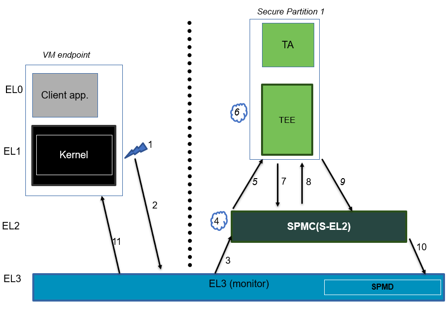
A brief description of the events:
Secure interrupt triggers while normal world is running.
FIQ gets trapped to EL3.
SPMD signals secure interrupt to SPMC at S-EL2 using FFA_INTERRUPT ABI.
SPMC identifies target vCPU of SP and injects virtual interrupt (pends vIRQ).
Assuming SP1 vCPU is in WAITING state, SPMC signals virtual interrupt using FFA_INTERRUPT with interrupt id as an argument and resumes the SP1 vCPU using ERET in SPMC scheduled mode.
Execution traps to vIRQ handler in SP1 provided that the virtual interrupt is not masked i.e., PSTATE.I = 0
SP1 queries for the pending virtual interrupt id using a paravirtualized HVC call. SPMC clears the pending virtual interrupt state management and returns the pending virtual interrupt id.
SP1 services the virtual interrupt and invokes the paravirtualized de-activation HVC call. SPMC de-activates the physical interrupt, clears the fields tracking the secure interrupt and resumes SP1 vCPU.
SP1 performs secure interrupt completion through FFA_MSG_WAIT ABI.
SPMC returns control to EL3 using FFA_NORMAL_WORLD_RESUME.
EL3 resumes normal world execution.
4.7.11.8. Actions for a secure interrupt triggered while execution is in secure world
State of target execution context |
Action |
Description |
WAITING |
Signaled |
This starts a new call chain in SPMC scheduled mode. |
PREEMPTED by Self S-Int |
Signaled |
The target execution context reenters the RUNNING state to handle the secure virtual interrupt. |
PREEMPTED by NS-Int |
Queued |
SPMC queues the secure virtual interrupt now. It is signaled when the target execution context next enters the RUNNING state. |
BLOCKED |
Signaled |
Both preempted and target execution contexts must have been part of the Normal world scheduled call chain. Refer scenario 1 of Table 8.4 in the FF-A v1.1 EAC0 spec. |
RUNNING |
NA |
The target execution context is running on a different CPU. This scenario is not supported by current SPMC implementation and execution hits panic. |
The following figure describes interrupt handling flow when a secure interrupt triggers while execution is in secure world. We assume OS kernel sends a direct request message to SP1. Further, SP1 sends a direct request message to SP2. SP1 enters BLOCKED state and SPMC resumes SP2.
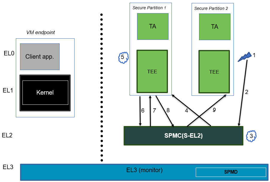
A brief description of the events:
Secure interrupt triggers while SP2 is running.
SP2 gets preempted and execution traps to SPMC as IRQ.
SPMC finds the target vCPU of secure partition responsible for handling this secure interrupt. In this scenario, it is SP1.
SPMC pends vIRQ for SP1 and signals through FFA_INTERRUPT interface. SPMC further resumes SP1 through ERET conduit. Note that SP1 remains in Normal world schedule mode.
Execution traps to vIRQ handler in SP1 provided that the virtual interrupt is not masked i.e., PSTATE.I = 0
SP1 queries for the pending virtual interrupt id using a paravirtualized HVC call. SPMC clears the pending virtual interrupt state management and returns the pending virtual interrupt id.
SP1 services the virtual interrupt and invokes the paravirtualized de-activation HVC call. SPMC de-activates the physical interrupt and clears the fields tracking the secure interrupt and resumes SP1 vCPU.
Since SP1 direct request completed with FFA_INTERRUPT, it resumes the direct request to SP2 by invoking FFA_RUN.
SPMC resumes the pre-empted vCPU of SP2.
4.7.11.9. EL3 interrupt handling
In GICv3 based systems, EL3 interrupts are configured as Group0 secure interrupts. Execution traps to SPMC when a Group0 interrupt triggers while an SP is running. Further, SPMC running at S-EL2 uses FFA_EL3_INTR_HANDLE ABI to request EL3 platform firmware to handle a pending Group0 interrupt. Similarly, SPMD registers a handler with interrupt management framework to delegate handling of Group0 interrupt to the platform if the interrupt triggers in normal world.
Platform hook
plat_spmd_handle_group0_interrupt
SPMD provides platform hook to handle Group0 secure interrupts. In the current design, SPMD expects the platform not to delegate handling to the NWd (such as through SDEI) while processing Group0 interrupts.
4.7.11.10. Inter-Processor Interrupts
Inter-Processor Interrupts (IPIs) are a mechanism for an SP to send an interrupt to to itself on another CPU in a multiprocessor system.
If an SP wants to send an IPI from vCPU0 on CPU0 to vCPU1 on CPU1 it uses the HVC paravirtualized interface HF_INTERRUPT_SEND_IPI, specifying the ID of vCPU1 as the target. The SPMC on CPU0 records the vCPU1 as the target vCPU the IPI is intended for, and requests the GIC to send a secure interrupt to the CPU1 (interrupt ID 9 has been assigned for IPIs). This secure interrupt is caught by the SPMC on CPU1 and enters the secure interrupt handler. Here the handling of the IPI depends on the current state of the target vCPU1 as follows:
RUNNING: The IPI is injected to vCPU1 and normal secure interrupt handling handles the IPI.
WAITING: The IPI is injected to vCPU1 and an SRI is triggered to notify the Normal World scheduler the SP vCPU1 has a pending IPI and requires cycles to handle it. This SRI is received in the Normal World on CPU1, here the notifications interface has been extended so that FFA_NOTIFICATION_INFO_GET will also return the SP ID and vCPU ID of any vCPUs with pending IPIs. Using this information the Normal World can use FFA_RUN to allocate vCPU1 CPU cycles.
PREEMPTED/BLOCKED: Inject and queue the virtual interrupt for vCPU1. We know, for these states, the vCPU will eventually resumed by the Normal World Scheduler and the IPI virtual interrupt will then be serviced by the target vCPU.
Supporting multiple services targeting vCPUs on the same CPU adds some complexity to the handling of IPIs. The intention behind the implementation choices is to fulfil the following requirements:
All target vCPUs should receive an IPI.
The running vCPU should be prioritized if it has a pending IPI, so that it isn’t preempted by another vCPU, just to be later run again to handle its IPI.
To achieve this, a queue of vCPUs with pending IPIs is maintained for each CPU. When handling the IPI SGI, the list of vCPUs with pending IPIs for the current CPU is emptied and each vCPU is handled as described above, fulfilling requirement 1. To ensure the running vCPU is prioritized, as specified in requirement 2, if there is a vCPU with a pending IPI in the WAITING state, and the current (running) vCPU also has a pending IPI, Hafnium will send the SRI at the next context switch to the NWd. This means the running vCPU can handle it’s IPI before the NWd is interrupted by the SRI to schedule the waiting vCPUs. If the current (running) vCPU does not have a pending IPI the SRI is immediately sent.
As an example this diagram shows the flow for an SP sending an IPI to a vCPU in the waiting state.
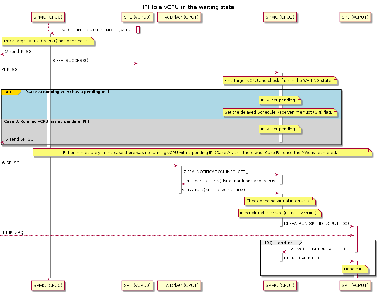
The transactions in the diagram above are as follows:
SP1 running on vCPU0 sends the IPI targeting itself on vCPU1 using the paravirtualised interface HF_INTERRUPT_SEND_IPI.
Hafnium records that there is a pending IPI for SP1 vCPU1 and triggers an IPI SGI, via the interrupt controller, for CPU1.
FFA_SUCCESS is returned to SP1 vCPU0 to show the IPI has been sent.
The interrupt controller triggers the IPI SGI targeted at CPU1. As described above, when handing the interrupt, the list of vCPUs on this CPU with pending IPIs is traversed. In the case of this example SP1 vCPU1 will be in the list and is in the WAITING state. If the current (RUNNING) vCPU also has a pending IPI then the flow follows the Case A on the diagram. Set the IPI virtual interrupt as pending on the target vCPU and set the delayed SRI flag for the current CPU. Otherwise the flow follows the Case B: simply set the IPI virtual interrupt as pending on the target vCPU.
For the Case B the SPM sends the Schedule Receiver Interrupt (SRI) SGI through the interrupt controller.
In both cases the interrupt controller will eventually send an SRI SGI targeted at CPU1. This will be received by the FF-A driver in the NWd.
This FF-A driver can use FFA_NOTIFICATION_INFO_GET to find more information about the cause of the SRI.
For this test, the IPI targeted at SP1 vCPU1 so this is returned in the list of partitions returned in FFA_SUCCESS.
From the information given by FFA_NOTIFICATION_INFO_GET, the FF-A driver knows to allocate SP1 vCPU1 cycles to handle the IPI. It does this through FFA_RUN.
Hafnium resumes the target vCPU and injects the IPI virtual interrupts.
The execution is preempted to the IRQ handlers by the pending virtual interrupt.
The SP calls HF_INTERRUPT_GET to obtain the respective interrupt ID.
Hafnium return the IPI interrupt ID via eret. Handling can then continue as required.
4.7.12. Power management
In platforms with or without secure virtualization:
The NWd owns the platform PM policy.
The Hypervisor or OS kernel is the component initiating PSCI service calls.
The EL3 PSCI library is in charge of the PM coordination and control (eventually writing to platform registers).
While coordinating PM events, the PSCI library calls backs into the Secure Payload Dispatcher for events the latter has statically registered to.
When using the SPMD as a Secure Payload Dispatcher:
A power management event is relayed through the SPD hook to the SPMC.
In the current implementation only cpu on (svc_on_finish) and cpu off (svc_off) hooks are registered.
The behavior for the cpu on event is described in Secondary cores boot-up. The SPMC is entered through its secondary physical core entry point.
The cpu off event occurs when the NWd calls PSCI_CPU_OFF. The PM event is signaled to the SPMC through a power management framework message. It consists in a SPMD-to-SPMC direct request/response (SPMC-SPMD direct requests/responses) conveying the event details and SPMC response. The SPMD performs a synchronous entry into the SPMC. Once the SPMC is entered:
It updates the internal state to reflect the physical core is being turned off.
It relays the PSCI CPU_OFF power management operation as a framework direct request message to the pinned execution context of the first MP SP provided:
The SP has subscribed to the CPU_OFF operation explicitly through its partition manifest. Refer to [6] for details of corresponding FF-A binding.
The pinned execution context is in the WAITING state.
Else, it sends a framework direct response to SPMD with success status code.
SPMC receives the direct response from the SP for the direct request framework message it had sent earlier.
If the status code in the message from SP is not SUCCESS, then SPMC sends a framework direct response to SPMD with DENIED status code. SPMD will eventually panic and stop the execution.
Else, SPMC continues to relay PSCI CPU_OFF power management operation to other subscribed MP SPs.
4.7.13. Arm architecture extensions for security hardening
Hafnium supports the following architecture extensions for security hardening:
Pointer authentication (FEAT_PAuth): the extension permits detection of forged pointers used by ROP type of attacks through the signing of the pointer value. Hafnium is built with the compiler branch protection option to permit generation of a pointer authentication code for return addresses (pointer authentication for instructions). The APIA key is used while Hafnium runs. A random key is generated at boot time and restored upon entry into Hafnium at run-time. APIA and other keys (APIB, APDA, APDB, APGA) are saved/restored in vCPU contexts permitting to enable pointer authentication in VMs/SPs.
Branch Target Identification (FEAT_BTI): the extension permits detection of unexpected indirect branches used by JOP type of attacks. Hafnium is built with the compiler branch protection option, inserting land pads at function prologues that are reached by indirect branch instructions (BR/BLR). Hafnium code pages are marked as guarded in the EL2 Stage-1 MMU descriptors such that an indirect branch must always target a landpad. A fault is triggered otherwise. VMs/SPs can (independently) mark their code pages as guarded in the EL1&0 Stage-1 translation regime.
Memory Tagging Extension (FEAT_MTE): the option permits detection of out of bound memory array accesses or re-use of an already freed memory region. Hafnium enables the compiler option permitting to leverage MTE stack tagging applied to core stacks. Core stacks are marked as normal tagged memory in the EL2 Stage-1 translation regime. A synchronous data abort is generated upon tag check failure on load/stores. A random seed is generated at boot time and restored upon entry into Hafnium. MTE system registers are saved/restored in vCPU contexts permitting MTE usage from VMs/SPs.
Realm Management Extension (FEAT_RME): can be deployed in platforms that leverage RME for physical address isolation. The SPMC is capable of recovering from a Granule Protection Fault, if inadvertently accessing a region with the wrong security state setting. Also, the ability to change dynamically the physical address space of a region, can be used to enhance the handling of
FFA_MEM_LENDandFFA_MEM_DONATE. More details in the section about Memory Sharing.
4.7.14. SIMD support
In this section, the generic term SIMD is used to refer to vector and matrix processing units offered by the Arm architecture. This concerns the optional architecture extensions: Advanced SIMD (formerly FPU / NEON) / SVE / SME.
The SPMC preserves the SIMD state according to the SMCCC (ARM DEN 0028F 1.5F section 10 Appendix C: SME, SVE, SIMD and FP live state preservation by the SMCCC implementation).
The SPMC implements the SIMD support in the following way:
SPs are allowed to use Advanced SIMD instructions and manipulate the Advanced SIMD state.
The SPMC saves and restores vCPU Advanced SIMD state when switching vCPUs.
SPs are restricted from using SVE and SME instructions and manipulating associated system registers and state. Doing so, traps to the same or higher EL.
Entry from the normal world into the SPMC and exit from the SPMC to the normal world preserve the SIMD state.
Corollary to the above, the normal world is free to use any of the referred SIMD extensions and emit FF-A SMCs. The SPMC as a callee preserves the live SIMD state according to the rules mentioned in the SMCCC.
This is also true for the case of a secure interrupt pre-empting the normal world while it is currently processing SIMD instructions.
SVE and SME traps are enabled while S-EL2/1/0 run. Traps are temporarily disabled on the narrow window of the context save/restore operation within S-EL2. Traps are enabled again after those operations.
4.7.14.1. Supported configurations
The SPMC assumes Advanced SIMD is always implemented (despite being an Arm optional architecture extension). The SPMC dynamically detects whether SVE and SME are implemented in the platform, then saves and restores the SIMD state according to the different combinations:
FEAT_AdvSIMD |
FEAT_SVE/FEAT_SVE2 |
FEAT_SME/FEAT_SME2 |
FEAT_SME_FA64 |
Y |
N |
N |
N |
Y |
Y |
N |
N |
Y |
Y |
Y |
N |
Y |
Y |
Y |
Y |
Y |
N |
Y |
N |
Y |
N |
Y |
Y |
Y: architectural feature implemented N: architectural feature not implemented
4.7.14.2. SIMD save/restore operations
The SPMC considers the following SIMD registers state:
Advanced SIMD consists of 32
Vn128b vectors. Vector’s lower 128b is shared with the larger SVE / SME variable length vectors.SVE consists of 32
Znvariable length vectors,Pxpredicates,FFRfault status register.SME when Streaming SVE is enabled consists of 32
Znvariable length vectors,Pxpredicates,FFRfault status register (when FEAT_SME_FA64 extension is implemented and enabled), ZA array (when enabled).Status and control registers (FPCR/FPSR) common to all above.
For the purpose of supporting the maximum vector length (or Streaming SVE
vector length) supported by the architecture, the SPMC sets SCR_EL2.LEN
and SMCR_EL2.LEN to the maximum permitted value (2048 bits). This makes
save/restore operations independent from the vector length constrained by EL3
(by ZCR_EL3), or the ZCR_EL2.LEN value set by the normal world itself.
For performance reasons, the normal world might let the secure world know it doesn’t depend on the SVE or SME live state while doing an SMC. It does so by setting the SMCCC SVE hint bit. In which case, the secure world limits the normal world context save/restore operations to the Advanced SIMD state even if either one of SVE or SME, or both, are implemented.
The following additional design choices were made related to SME save/restore operations:
When FEAT_SME_FA64 is implemented,
SMCR_EL2.FA64is set and FFR register saved/restored when Streaming SVE mode is enabled.For power saving reasons, if Streaming SVE mode is enabled while entering the SPMC, this state is recorded, Streaming SVE state saved and the mode disabled. Streaming SVE is enabled again while restoring the SME state on exiting the SPMC.
The ZA array state is left untouched while the SPMC runs. As neither SPMC and SPs alter the ZA array state, this is a conservative approach in terms of memory footprint consumption.
4.7.15. SMMUv3 support in Hafnium
An SMMU is analogous to an MMU in a CPU. It performs address translations for Direct Memory Access (DMA) requests from system I/O devices. The responsibilities of an SMMU include:
Translation: Incoming DMA requests are translated from bus address space to system physical address space using translation tables compliant to Armv8/Armv7 VMSA descriptor format.
Protection: An I/O device can be prohibited from read, write access to a memory region or allowed.
Isolation: Traffic from each individial device can be independently managed. The devices are differentiated from each other using unique translation tables.
The following diagram illustrates a typical SMMU IP integrated in a SoC with several I/O devices along with Interconnect and Memory system.
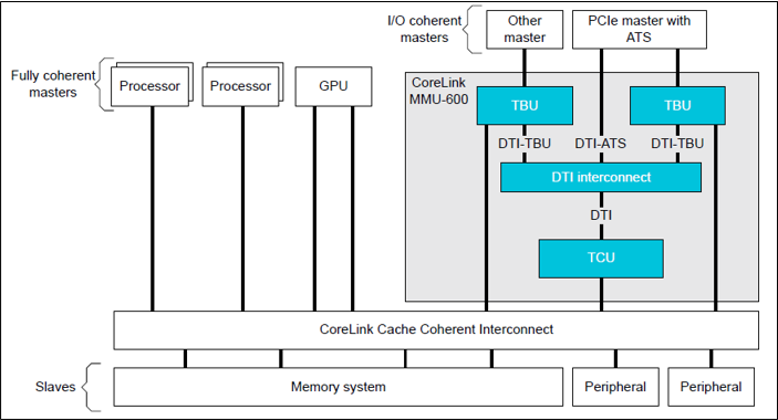
SMMU has several versions including SMMUv1, SMMUv2 and SMMUv3. Hafnium provides support for SMMUv3 driver in both normal and secure world. A brief introduction of SMMUv3 functionality and the corresponding software support in Hafnium is provided here.
4.7.15.1. SMMUv3 features
SMMUv3 provides Stage1, Stage2 translation as well as nested (Stage1 + Stage2) translation support. It can either bypass or abort incoming translations as well.
Traffic (memory transactions) from each upstream I/O peripheral device, referred to as Stream, can be independently managed using a combination of several memory based configuration structures. This allows the SMMUv3 to support a large number of streams with each stream assigned to a unique translation context.
Support for Armv8.1 VMSA where the SMMU shares the translation tables with a Processing Element. AArch32(LPAE) and AArch64 translation table format are supported by SMMUv3.
SMMUv3 offers non-secure stream support with secure stream support being optional. Logically, SMMUv3 behaves as if there is an indepdendent SMMU instance for secure and non-secure stream support.
It also supports sub-streams to differentiate traffic from a virtualized peripheral associated with a VM/SP.
Additionally, SMMUv3.2 provides support for PEs implementing Armv8.4-A extensions. Consequently, SPM depends on Secure EL2 support in SMMUv3.2 for providing Secure Stage2 translation support to upstream peripheral devices.
4.7.15.2. SMMUv3 Programming Interfaces
SMMUv3 has three software interfaces that are used by the Hafnium driver to configure the behaviour of SMMUv3 and manage the streams.
Memory based data strutures that provide unique translation context for each stream.
Memory based circular buffers for command queue and event queue.
A large number of SMMU configuration registers that are memory mapped during boot time by Hafnium driver. Except a few registers, all configuration registers have independent secure and non-secure versions to configure the behaviour of SMMUv3 for translation of secure and non-secure streams respectively.
4.7.15.3. Peripheral device manifest
Currently, SMMUv3 driver in Hafnium only supports dependent peripheral devices. These DMA devices are dependent on PE endpoint to initiate and receive memory management transactions on their behalf. The acccess to the MMIO regions of any such device is assigned to the endpoint during boot. The device node of the corresponding partition manifest must specify these additional properties for each peripheral device in the system:
smmu-id: This field helps to identify the SMMU instance that this device is upstream of.
stream-ids: List of stream IDs assigned to this device.
smmuv3-testengine {
    base-address = <0x00000000 0x2bfe0000>;
    pages-count = <32>;
    attributes = <0x3>;
    smmu-id = <0>;
    stream-ids = <0x0 0x1>;
    interrupts = <0x2 0x3>, <0x4 0x5>;
    exclusive-access;
};
4.7.16. DMA isolation
Hafnium, with help of SMMUv3 driver, enables the support for static DMA isolation. The DMA device is explicitly granted access to a specific memory region only if the partition requests it by declaring the following properties of the DMA device in the memory region node of the partition manifest:
smmu-id
stream-ids
stream-ids-access-permissions
SMMUv3 driver uses a unqiue set of stage 2 translations for the DMA device rather than those used on behalf of the PE endpoint. This ensures that the DMA device has a limited visibility of the physical address space.
smmuv3-memcpy-src {
    description = "smmuv3-memcpy-source";
    pages-count = <4>;
    base-address = <0x00000000 0x7400000>;
    attributes = <0x3>; /* read-write */
    smmu-id = <0>;
    stream-ids = <0x0 0x1>;
    stream-ids-access-permissions = <0x3 0x3>;
};
4.7.16.1. SMMUv3 driver limitations
The primary design goal for the Hafnium SMMU driver is to support secure streams.
Currently, the driver only supports Stage2 translations. No support for Stage1 or nested translations.
Supports only AArch64 translation format.
No support for features such as PCI Express (PASIDs, ATS, PRI), MSI, RAS, Fault handling, Performance Monitor Extensions, Event Handling, MPAM.
No support for independent peripheral devices.
4.7.17. S-EL0 Partition support
The SPMC (Hafnium) has limited capability to run S-EL0 FF-A partitions using FEAT_VHE (mandatory with ARMv8.1 in non-secure state, and in secure world with ARMv8.4 and FEAT_SEL2).
S-EL0 partitions are useful for simple partitions that don’t require full Trusted OS functionality. It is also useful to reduce jitter and cycle stealing from normal world since they are more lightweight than VMs.
S-EL0 partitions are presented, loaded and initialized the same as S-EL1 VMs by the SPMC. They are differentiated primarily by the ‘exception-level’ property and the ‘execution-ctx-count’ property in the SP manifest. They are host apps under the single EL2&0 Stage-1 translation regime controlled by the SPMC and call into the SPMC through SVCs as opposed to HVCs and SMCs. These partitions can use FF-A defined services (FFA_MEM_PERM_*) to update or change permissions for memory regions.
S-EL0 partitions are required by the FF-A specification to be UP endpoints, capable of migrating, and the SPMC enforces this requirement. The SPMC allows a S-EL0 partition to accept a direct message from secure world and normal world, and generate direct responses to them. All S-EL0 partitions must use AArch64. AArch32 S-EL0 partitions are not supported.
Interrupt handling, Memory sharing, indirect messaging, and notifications features in context of S-EL0 partitions are supported.
4.7.18. Support for arch timer and system counter
Secure Partitions can configure the EL1 physical timer (CNTP_*_EL0) to generate a virtual interrupt in the future. SPs have access to CNTPCT_EL0 (system count value) and CNTFRQ_EL0 (frequency of the system count). Once the deadline set by the timer expires, the SPMC injects a virtual interrupt (ID=3) and resumes the SP’s execution context at the earliest opportunity as allowed by the secure interrupt signaling rules outlined in the FF-A specification. Hence, it is likely that time could have passed between the moment the deadline expired and the interrupt is subsequently signaled.
Any access from an SP to EL1 physical timer registers is trapped and emulated by SPMC behind the scenes, though this is completely oblivious to the SP. This ensures that any EL1 physical timer deadline set by a normal world endpoint is not overriden by either SPs or SPMC.
Note
As per Arm ARM, assuming no support for FEAT_ECV, S-EL1 has direct access to EL1 virtual timer registers but S-EL0 accesses are trapped to higher ELs. Consequently, any attempt by an S-EL0 partition to access EL1 virtual timer registers leads to a crash while such an attempt by S-EL1 partition effectively has no impact on its execution context.
4.7.19. Partition Lifecycle support
Partition lifecycle describes the various states a vCPU of a partition goes through from when it is created till it is destroyed or restarted. Any state transition of a vCPU is explicitly managed by SPMC as per the rules described in Chapter 7 of the FF-A v1.3 ALP2 spec.
It is important to note that the state of a SP’s vCPU is maintained by SPMC but is invisible to any other entity outside of SPMC.
SPMC uses partition lifecycle to enable the use case of fault handling when an SP encounters a fatal error during its execution. In addition to involuntary fatal errors, an SP can voluntarily abort its execution using the FFA_ABORT ABI.
A v1.3 compliant SP declares support for partition lifecycle through its partition manifest. The FF-A spec allows SPs to optionally specify the action taken by SPMC if any vCPU encounters a fatal error or aborts execution voluntarily. Refer to the binding document [6] for the various abort actions supported by hafnium.
4.7.20. Support for live activation of Secure Partitions
Live firmware activation updates a Secure Partition without rebooting the platform, minimizing disruption in scenarios such as code patching secure services in data-center or cloud deployments. Hafnium follows the guidance in the FF-A v1.3 ALP2 specification to implement this feature in coordination with an LSP managed by the SPMD in EL3.
Live activation currently has the following prerequisites:
The SP must opt into partition lifecycle support.
The current and target SP images must be compatible.
Only uniprocessor SPs (single execution context) are supported.
If any prerequisite fails, the SPMC rejects the request. Hafnium currently requires that the old and new partition manifests are identical. This helps to keep the implementation simpler and ensures the properties of old and new manifests are compatible with each other.
4.7.20.1. Working memory region and staged packages
During cold boot, TF-A allocates a chunk of physical address space to each Secure Partition image (package), referred to as the working memory region. It’s base address is platform-defined, specified as load-address in the SPMC manifest.
Hafnium updates partitions in place: the staged package overwrites the existing package in the working memory region. Therefore, the framework state must never reside inside that region. If overlap is detected, the SPMC rejects the request and aborts the partition.
On a successful live activation, the SPMC guarantees that:
Framework state persists.
RX/TX buffers remain mapped at the same VA/IPA (provided they avoid the working memory region) and their contents are preserved.
VM and SP notification bindings remain intact.
Pending VM, SP, and framework notifications are preserved.
Memory regions shared or lent by other endpoints keep their VA/IPA and memory attributes.
Metadata for in-flight memory management transactions is preserved so the new image can resume operating on them.
Platform integrators must also declare a live-state buffer under the
memory-regions node in the partition manifest; refer to the binding
document [6] for the full schema and a minimal manifest excerpt.
4.8. References
[1] Arm Firmware Framework for Arm A-profile
[2] Secure Partition Manager using MM interface
[3] Trusted Boot Board Requirements Client
[5] https://git.trustedfirmware.org/TF-A/tf-a-tests.git/tree/spm/cactus/plat/arm/fvp/fdts/cactus.dts
[6] https://trustedfirmware-a.readthedocs.io/en/latest/components/ffa-manifest-binding.html
[10] https://trustedfirmware-a.readthedocs.io/en/latest/getting_started/build-options.html#
[11] https://developer.arm.com/documentation/den0140/a
[12] https://developer.arm.com/documentation/den0129/latest/
Copyright (c) 2020-2023, Arm Limited and Contributors. All rights reserved.